Manual of Ultra Fine Pulverizer
Part One: The Main Structures and Operating Principle
1. Introduction to main structures
This equipment consists of frame housing, main shaft assembly, grinding chamber, grading assembly, screw conveyor, main transmission assembly, grading transmission assembly, air supply system, airlock motor, fan, cyclone separator and cloth bag-type dust collector. Variable speed motor and screw conveyor motor with inverter for variable speed control. Grinding chamber contains grinding disc, beater, grinding ring and diverter ring. Grading assembly contains grading impeller, grading shaft and discharge outlet, is located above the grinding chamber. The top variable speed motor powers the grading impeller. Discharge outlet of main shaft assembly connected to cyclone separator, airlock motor, high pressure centrifugal fan and dust collector.
2. Operating principle
Refer to the principle drawing of ultra-fine grinding
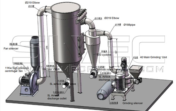
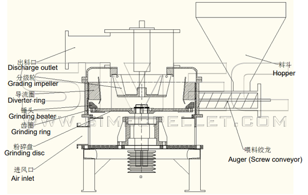
The screw conveyor carries a fixed quantity of materials that is less than 5mm into grinding chamber. In the grinding chamber, the high-speed grinding disc creates centrifugal force on the materials that resulted in being hammered by the beaters at the grinding disc, and the grinding ring, to form size reduction.
When the size gradually reduces, the material floating force inside the grinding chamber decreases, the induced draft fan creates an air force carrying the fine particles from the grinding disc into the grading assembly for separation. The mixed particles at the forces of the aerodynamics and impeller centrifugation, the particle sizes that are less than critical diameter (target diameter) is sucked into the grading impeller, then subsequently going into the product collector through the outlet; those particle sizes that are bigger than critical diameter returns to grinding chamber through diverter ring.
The material is continuously going into grinding chamber, and continuously separation by grading assembly and sending to grading impeller for those less than critical diameter, then sucked into product collector. The process can reach the desired size reduction. The grinding particle sizes can be adjusted through the speed of grading impeller and air volume.
Part Two: The Key Features and Characteristics
1. Not sieve screen design, micro crushing and micro powder separation processes at the same time, save crushing/grinding energy, reduce vibration.
2. The grinding disc and grading impeller are separately powered, reducing the mass pressure on the main driving shaft, and increasing air cooling.
3. Due to machine compact design, good layout, quality of materials use, the main wearing parts, such as grinding beater and grinding ring, are of alloyed composites to extend the life span, but relatively lower cost than other similar product in the market.
4. Low in heat generation when grinding material, keeping the product in original form, high efficiency, low electricity consumption.
5. Can adjust the feeding auger speed and grinding particle size when machine is running.
6. The machine gets high grinding throughput (100-6000 kg/h), fine powder (900-60 mesh), low power consumption, long life span, good dust collection.
7. Installed a strong magnetic device to remove iron particles at the entrance of auger to protect the normal operating of the machine.
Part Three: The Key Operating Parameters
Model: SCW30
The main grinding motor power: 30 kW
The grading motor power: 3 kW
Centrifugal fan motor power: 11 kW
Auger screw motor power: 0.55 kW
Airlocks x2 motor power: 0.75 kW
Part Four: Installation and Adjustment
1. Each part of equipment should be connected firmly, and the pipe joints should be tightened to prevent air leakage. If the seal is not tight enough, it will not only produce dust pollution, but also reduce the production capacity and product quality.
2. The electrical control cabinet should be placed in a location for convenient operation and easy to monitor the operation of the equipment. The electrical connection cables between the parts of equipment should be placed in a conduit pipe according to the relevant national regulations.
3. Electrical control cabinet is equipped with On and Off Switches, work indicator light, grinding motor current, indication meters and various overload electrical protection devices.
4. The Start and Stop operating sequence of the equipment:
4.1. Start the high-pressure fan and airlock motor, observe the air pressure and air volume are within the specified range, otherwise the damper valve should be adjusted to achieve the target range.
4.2. Start the grading motor. Check that the grading impeller speed is within the specified range. The rotation direction should be opposite of the grinding disc direction.
4.3. Start the grinding motor, observe whether it is a smooth operation.
4.4. Start the auger screw motor and control the feeding volume to ensure the particle size and yield of the product are correct.
4.5. Stopping sequence: Switch off the Auger screw motor and wait until the material in grinding chamber is empty, and then switch off the main grinding motor. Wait until the grinding disc completely stops, and then switch off in the sequence of the grading motor, fan motor, airlock motors (x2) and power supply turned off.
5. The micro particle size produced by this machine can be adjusted to some degree, according to user requirements. When adjusting, take out the powder sample and sieve the samples with the corresponding measuring sieve. If the product size is too big, the grading impeller speed can be increased gradually until it meets the requirements. However, if the product size is too small, the grading impeller speed can be reduced.
6. When the product particle size reaches the requirement, then adjust the main grinding motor load current by observing the Amp meter. If the load current is too high or too low, increase or decrease the speed of feed auger screw motor to change the feed volume, so that the main motor load is in a smooth-running condition.
7. The pulse dust collector is normally pulse blown under the following conditions in order to increase the service life of the pulse solenoid valves and filter bags:
a). When the pressure difference between the inlet and outlet of the pulse dust collector reaches a certain value, (200mmH2O); or
b). When the fan current drops to a certain value.
8. When processing heat-sensitive materials, the main grinding motor load should be adjusted to slightly lower than the rated power.
9. The required air volume in the pipeline can be achieved by adjusting the damper opening of the induced draft fan. When the air volume increases, the product size becomes large, but the output increases, and vice versa. The air volume is generally set and does not require to be adjusted after getting the balance of product size and production throughout as required.
10. The tension of the v-belts should be checked regularly to prevent slipping on the belt pulleys.
Part Five: Safety Operation Rules
1. The raw materials to be ground in this machine must not contain any metals, stones, hard debris, etc.. If these foreign impurities and debris get into the grinding chamber, it will cause serious damage to the machine.
2. Before starting the machine, a complete check must be carried out on the connection joints that must be firmly joined and tightly sealed. The grinding chamber must not have any metal debris in it. Any such debris must be removed before starting the machine.
3. Before Inspection and maintenance of any internal working parts of this machine, you must isolate the power supply first completely and ensure it has stopped rotating. Open the top cover or main cover for maintenance or inspection.
4. The rotating direction of each motor should be clearly marked and labelled, and the wiring should be rotated in the indicated direction.
5. Lubrication and refilling oil/grease must be strictly followed in accordance with the lubrication schedules, and must be filled with the grease and oil specifically supplied for this machine. It is strictly prohibited to mix with other grease.
6. Before starting the machine, test the moisture content in the raw materials to be ground and they must be within the specified range, so as not to affect product quality and production efficiency.
Part Six: Maintenance and Services
1. Do not spill water on the motor and bearing seal when cleaning the grinding chamber.
2. When replacing damaged parts or under taking maintenance, the main electrical switch must be OFF first and hang the "Do not Turn On" sign, then disassemble the machine according to the following order:
2.1. After opening the top cover, remove the top nut of the main shaft, and then take out the grading impeller. Care must be taken not to bend the grading blades when removing, so as not to affect the balance of the grading impeller.
2.2. Unscrew the supporting rod and remove the diverter ring.
2.3. Remove the nut and take out the grinding disc.
2.4. If needing to clean the bearings or replace the bearings, these can be pulled out from the bottom of the machine grinding rotor assembly, placed on the workbench, and remove the two pulleys, seals and retaining rings, and then pull out the grading impeller shaft and grinding spindle. Clean and check the bearings and seals.
2.5. If needing to disassemble the feeding device, you should first remove the belts by loosening the coupling bolts.
3. Regularly and irregularly check the wear & tear of the grinding chamber parts.
The normal wear replacement time of a wearing parts needs to be determined according to the nature of different materials characteristics, hardness and use time. The wearing parts (grinding beater, grinding ring) needs to be strictly controlled and monitored their degree of wearing. When these parts are wearied to have affected the fixed coupling bolts, they should be replaced in a timely manner. Otherwise, they may fall off and break the entire grinding chamber, resulting in some accidents.
4. Lubrications
Bearing lubrication must use high-speed special lubricating grease specially matched with this machine. the amount of use is about one-third of the bearing circle. The frequency of the lubricant change as:
The first change is 100 working hours; then
The second change is 500 working hours;
After that, the grease should be changed once every 1000 working hours.
There are two grease nozzles on the bearing of the main grinding unit which should be refilled with grease gun once every 30 working hours.
5. Wearing parts
The standard wearing parts need to be purchased separately.
List of wearing parts:
Grinding ring 1 pc
Tool 1 set
Grinding disk 1 pc
Grading impeller 1 pc
Main shaft 1 pc
Grading shaft 1 pc
Part Seven: Common Troubleshooting Methods
| NO | SYMPTOM | POSSIBLE OF CAUSE | POSSIBLE OF SOLUTIONS |
| 1 | The grading impeller rotates with the main shaft, and the speed cannot be adjusted. |
|
1. Clean the bearing and refill grease, with a dosage of 1/3 of the bearing ring using the machine's special lubricating grease. 2. Check the fitting accuracy of relevant parts and replace or adjust as require. 3. Change the direction of rotation and operate according to the starting sequence. |
| 2 | The materials are sprayed out from the suction pipe at the top of the grinding unit in the grinding room. |
1. Material blockage grinding chamber. 2. Insufficient pressure generated from centrifugal fan |
1. Identify the cause of the blockage and reduce the feeding amount. 2. Check the dust collector is clean and eliminate the dust bag blockage. |
| 3 | Productivity decline |
1. Grinding belt slipping. 2. Grinding blades worn. 3. Machine is blockage. |
1. Tensioning the belt. 2. Replace the grinding blades. 3. Clear blockage. |
| 4 | Finished product too fine or too coarse | 1. The speed of the grading impeller is too high or too low. | 1. Adjusting the speed of the grading impeller. |
| 5 | Grinder unit has high vibration |
1. Grinding disc imbalance. 2. Bearing damage. |
1. Balanced the grinding disc. 2. Replace the bearings and tighten the connecting bolts. |
| 6 | The motor cannot start |
1. Electrical protection action. 2. Electrical components damaged. |
1. Inspect and resolve the action, replace the fuse. 2. Check the electrical cables and replace the electrical components. |
| 7 | Bearing heat exceeds allowable temperature |
1. Lack of grease or too much grease. 2. Bearing installation error 3. Overloaded operation. |
1. Check the amount of grease added, 1/3 of the bearing ring. 2. Re-check and adjust the mounting bearing to ensure the accurate installation. |
| 8 | Reduced the rotation speed of the main shaft spindle |
1. Overload or intake material particle size is too large. 2. Material is blocked and getting stuck. 3. Driving belts are loose. |
1. Control the feeding speed from auger screw. Prevent large pieces of material entering into grinding chamber. 2. Stop feeding and/or stop machine for inspection and clear any blockage as necessary. 3. Adjust and tighten the belts. |
| 9 | Abnormal machine sound |
1. Metals in feed materials 2. Loose or damaged coupling bolt in the grinding chamber |
1. Carefully inspect or replace feed materials with adding catching screen to catch foreign debris. Installing magnetic devise. 2. Inspection, fastening or replacing coupling bolts. |
| 10 | Feed auger screw motor stops | 1. Foreign debris and hard materials sucked into motor or jammed the auger screw system | 1. inspect and control the feed materials particle size, and removed as necessary. |
| 11 | Auger screw stops | 1. Stuck the auger turn due to feed intake materials containing too coarse and hard particles or foreign objects | 1. Inspect and control the feed materials particle size, and removed as necessary. |
| 12 | Poor Dust removal and air exhaust obstructed | 1. The severely clogged in the cloth bag-type dust collector | 1. Tap the dust bag to remove or loose clogged dust. |
For more information, please contact SIMEC.
Email: info@simecpellet.com
Tel: +86 372 5375806
*Copyright of the contents and photos in this brochure belongs to SIMEC.
*We reserve the right to make changes in technical aspects, material and specifications without prior notice.